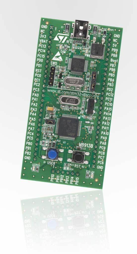
ST STM32VL Discovery
Overview
The STM32 Discovery series comes in many varieties, in this case the “Value Line” STM32F100x SoC series is showcased. Like other Discovery board, an integrated ST-LINK debugger and programmer is included (V1), but the only included I/O devices are two user LEDs and one user button.

More information about the board can be found at the STM32VLDISCOVERY website 1.
Hardware
The STM32 Discovery board features:
On-board ST-LINK/V1 with selection mode switch to use the kit as a standalone ST-LINK/V1 (with SWD connector for programming and debugging)
Board power supply: through USB bus or from an external 5 V supply voltage
External application power supply: 3 V and 5 V
Four LEDs:
LD1 (red) for 3.3 V power on
LD2 (red/green) for USB communication
LD3 (green) for PC9 output
LD4 (blue) for PC8 output
Two push buttons (user and reset)
Extension header for all LQFP64 I/Os for quick connection to prototyping board and easy probing
More information about the STM32F100x can be found in the STM32F100x reference manual 2 and the STM32F100x data sheet 3.
Supported Features
The Zephyr stm32vl_disco board configuration supports the following hardware features:
Interface |
Controller |
Driver/component |
|---|---|---|
NVIC |
on-chip |
nested vector interrupt controller |
UART |
on-chip |
serial port-polling serial port-interrupt |
PINMUX |
on-chip |
pinmux |
GPIO |
on-chip |
gpio |
CLOCK |
on-chip |
reset and clock control |
FLASH |
on-chip |
flash memory |
WATCHDOG |
on-chip |
window watchdog |
I2C |
on-chip |
i2c |
SPI |
on-chip |
spi |
ADC |
on-chip |
adc |
Other hardware features are not yet supported in this Zephyr port.
The default configuration can be found in the defconfig file:
boards/arm/stm32vl_disco/stm32vl_disco_defconfig
Connections and IOs
Each of the GPIO pins can be configured by software as output (push-pull or open-drain), as input (with or without pull-up or pull-down), or as peripheral alternate function. Most of the GPIO pins are shared with digital or analog alternate functions. All GPIOs are high current capable except for analog inputs.
Default Zephyr Peripheral Mapping:
UART_1_TX : PA9
UART_1_RX : PA10
UART_2_TX : PA2
UART_2_RX : PA3
UART_3_TX : PB10
UART_3_RX : PB11
SPI1_NSS : PA4
SPI1_SCK : PA5
SPI1_MISO : PA6
SPI1_MOSI : PA7
SPI2_NSS : PB12
SPI2_SCK : PB13
SPI2_MISO : PB14
SPI2_MOSI : PB15
I2C1_SCL : PB6
I2C1_SDA : PB7
I2C2_SCL : PB10
I2C2_SDA : PB11
For mode details please refer to STM32VLDISCOVERY board User Manual 4.
Programming and Debugging
Applications for the stm32vl_disco board configuration can be built and
flashed in the usual way (see Building an Application and
Run an Application for more details).
Flashing
STM32VLDISCOVERY board includes an ST-LINK/V1 embedded debug tool interface. This interface is supported by the openocd version included in the Zephyr SDK.
Flashing an application
Here is an example for the Blinky application.
# From the root of the zephyr repository
west build -b stm32vl_disco samples/basic/blinky
west flash
You will see the LED blinking every second.
Debugging
You can debug an application in the usual way. Here is an example for the Blinky application.
# From the root of the zephyr repository
west build -b stm32vl_disco samples/basic/blinky
west debug
USB mass storage issues
The ST-LINK/V1 includes a buggy USB mass storage gadget. To connect to the ST-LINK from Linux, you might need to ignore the device using modprobe configuration parameters:
$ echo "options usb-storage quirks=483:3744:i" | sudo tee /etc/modprobe.d/local.conf
$ sudo modprobe -r usb-storage