Evaluation Board Setup (PCA10001/PCA10003)
The following instructions describe how to set up the Evaluation Board:
- Connect the Evaluation Board to the PC.
If you are using SoftDevice S110 (Bluetooth):
- Program the S110 SoftDevice (see the nRF51822 EK User Guide).
- Connect the Master Emulator (nRF2739) to the PC.
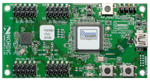
Evaluation Board Setup
For all examples the same hardware setup is used.
Some of the GPIO pins are already defined to have a special purpose:
- PIN 8 - is used for UART RTS
- PIN 9 - is used for UART TX
- PIN 10 - is used for UART CTS
- PIN 11 - is used for UART RX
- PIN 16 - is used for BUTTON0
- PIN 17 - is used for BUTTON1
- PIN 18 - is used for LED0
- PIN 19 - is used for LED1
Configure your terminal application for 38400 bauds, 8 data bits, 1 stop bit and Flow Control RTS/CTS enabled.
nRFgo Motherboard Setup (nRF6310)
The following instructions describe how to set up the nRFgo Motherboard (the names in bold refer to the silk print on the Motherboard):
- Mount nRFgo carrier board and the PCA10004/PCA10005 module.
- Connect a 10p flat cable (2.54 mm, included in nRFgo Starter Kit) from PORT0 to the BUTTONS connector. In doing so, ensure that P0.0 is connected to BUTTON 1.
- Connect another 10p flat cable (2.54 mm, also included in nRFgo Starter Kit) from PORT1 to the LEDS connector. In doing so, ensure that P1.0 is connected to LED 1. (Refer to the image in 'Connect the hardware' section of the 'Getting Started Guide' to see this connection)
- Connect a 2p cable from RX-TX to P2.0 and P2.1, so that RX is connected to P2.0 and TX is connected to P2.1.
- Connect a 2p cable from P3.0-P3.1 to SDA-SCL, so that P3.0 is connected to SCL and P3.1 is connected to SDA in the display extension board.
- Connect the nRFgo Motherboard (nRF6310) to the PC using a USB cable.
If you are using SoftDevice S110 (Bluetooth):
- Program the S110 SoftDevice (see the nRF51822 DK User Guide).
- Connect the Master Emulator (nRF2739) to the PC.
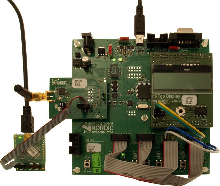
nRFgo Motherboard Setup
For all examples the same hardware setup is used.
Some of the GPIO pins are already defined to have a special purpose:
- PIN 0 to 7 - is used for buttons (Named P0.0-P0.7 on the nRF6310 Motherboard).
- PIN 8 to 15 - is used for LEDs (Named P1.0-P1.7 on the nRF6310 Motherboard).
- PIN 16 - is used for serial RX (P2.0 on the nRF6310 Motherboard).
- PIN 17 - is used for serial TX (P2.1 on the nRF6310 Motherboard).
- PIN 24 - is used for display clock - SCL (P3.0 on the nRF6310 Motherboard).
- PIN 25 - is used for display data - SDA (P3.1 on the nRF6310 Motherboard).
Configure your terminal application for 38400 bauds, 8 data bits and 1 stop bit. The nRF6310 examples do not use any flow control.

 1.8.3.1
