 |
nRF51 SDK - S120 SoftDevice
|
 |
nRF51 SDK - S120 SoftDevice
|
The general purpose Input/Output is organized in the nRF51 series chips as one port with up to 32 I/Os (dependent on package) enabling access and control of up to 32 pins through one port. In most applications, the state of a GPIO or a change in state of a GPIO may trigger an application to take action or transition to another state.
The GPIO Tasks and Events (GPIOTE) provides functionality for accessing GPIO pins using tasks and events. The GPIO Task & Events (GPIOTE) library referred to as the the 'app_gpiote' in the SDK, facilitates application(s) to register for notification of change in state of one or more pins.
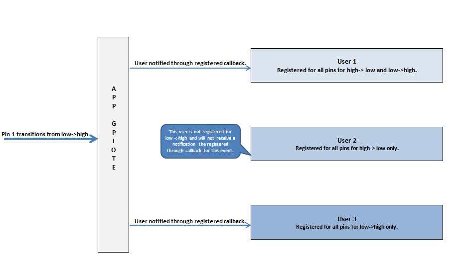
Since an application can consist of multiple independent modules, GPIOTE library allows several components to share the GPIOTE interrupt,each user defining a set of pins able to generate events to the user. When a GPIOTE interrupt occurs, the GPIOTE interrupt handler will identify pin transition(S) and notify each client registered for the transition.

The GPIOTE users are responsible for configuring all their corresponding pins, except the SENSE field, which should be initialized to GPIO_PIN_CNF_SENSE_Disabled.
The module specifies on which pins events should be generated if the pin(s) goes from low->high or high->low or both directions.
The initialization procedure must be performed before using any of the other APIs of the module. It is recommended to use initialization macro APP_GPIOTE_INIT instead of the routine app_gpiote_init as the former takes care of reserving needed memory for the each user requested in the MAX_USERS parameter of the macro. This parameter indicates how may users are going to be registering with the library.
Each user must register itself with the module to be notified of change in state of GPIO. During registry, the user must provide callback handler to notify of a transition event and pin transitions its is interested in. 32-bit bitmask is used to represent 32 GPIO pins as shown in Figure 2 below. User can register for transition from high to low and/or low to high.

On successful registration, the user is assigned a user id and the user is expected to remember this identifier for all subsequent requests made to the module. This identifier is provided in the out parameter p_user_id. A sample registration is shown below.
By default, the GPIOTE is disabled on initialization. Therefore the GPIOTE has to be enabled by one of the users to start receiving GPIOTE state events. app_gpiote_user_enable is used to enable GPIOTE.
The following is a sample of registered user callback handling pin transition events.
The GPIOTE module can be enabled or disabled by a registered user at any point of time. No state transition events are received when the GPIOTE is disabled. On initialization, by default, the GPIOTE is disabled.
The following code snippet disables and enables the GPIOTE.
A registered user can read the current state of GPIOs by reading the state information. The following code snippets demonstrates a module reading the state information.