 |
nRF51 SDK
|
 |
nRF51 SDK
|
The Stride and Distance Monitor (SDM) slave implements all of the features, which are required for the receiver to be compliant with the ANT+ SDM profile, as defined by the ANT+ SDM specification:
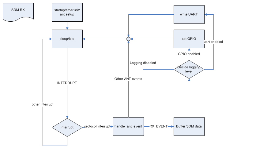
The process flow of the SDM RX example is illustrated below:

For logging UART will be the primary display. Data will be printed after broadcast data is received. Depending on the page received, the following data will be logged:
The logging with UART will be enabled by default in the project file. This can be deactivated by removing TRACE_UART from the compiler flags. When deactivated the data processing function will not be included in the compilation, as there are no need to interpret the data received, when we can not display the information.
As UART will use some extra current, a low power alternative is also available, using GPIO. By default the GPIO pins are connected to LEDs when using the PCA10003 ev-kit board or with nRF6310 with setup A. Also GPIO logging is enabled by default by the project file. This can be deactivated by removing TRACE_GPIO from the compiler flags. The GPIO pins to be used can be changed by editing the GPIO defines.
When GPIO logging is enabled the following GPIO will toggle:
When using PCA10003 board this board only have two leds. SDM_GPIO_2 will not be connected to any LED, but could be monitored by a logic analyzer or such.
The Stride and Distance Monitor (SDM) master implements all of the features, which are required for the transmitter to be compliant with the ANT+ SDM profile, as defined by the ANT+ SDM specification:
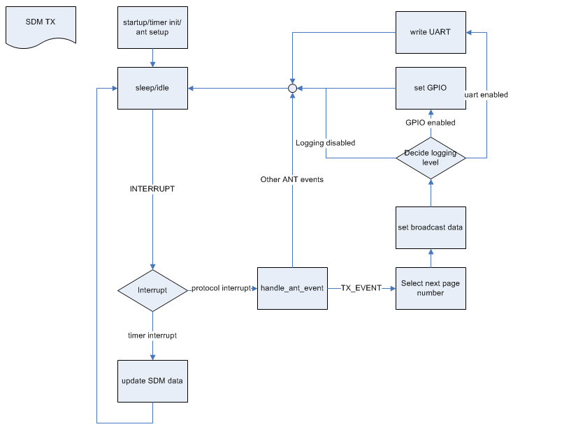
The process flow of the SDM TX example is illustrated below:

For logging UART will be the primary display. Data will be printed after broadcast data is set. Depending on the page transmitted, the following data will be logged:
The logging with UART will be enabled by default in the project file. This can be deactivated by removing TRACE_UART from the compiler flags.
As UART will use some extra current, a low power alternative is also available, using GPIO. By default the GPIO pins are connected to LEDs when using the PCA10003 ev-kit board or with nRF6310 with setup A. Also GPIO logging is enabled by default by the project file. This can be deactivated by removing TRACE_GPIO from the compiler flags. The GPIO pins to be used can be changed by editing the GPIO defines.
When GPIO logging is enabled the following GPIO will toggle: