 |
nRF51 SDK - S130 SoftDevice
|
 |
nRF51 SDK - S130 SoftDevice
|
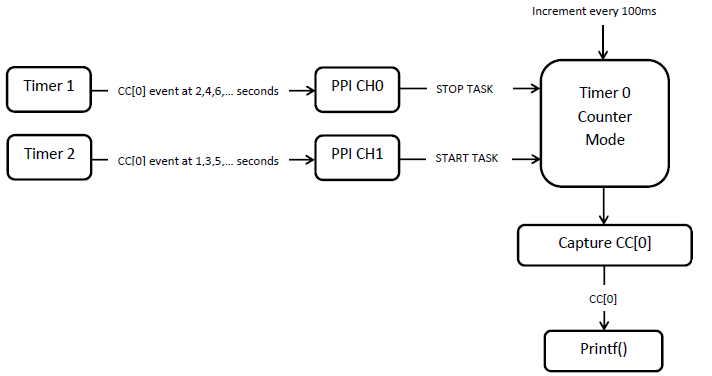
The Programmable Peripheral Interconnect (PPI) Example uses the PPI module to communicate between three timers.
Timer 0 is triggered by the main program loop every 100 milliseconds. The counter value of timer 0 is passed through the UART port and can be observed with a COM listener like, for example, PUTTY.
Timer 1 generates events every even second, thus at 2, 4, 6, 8, ... seconds. These events trigger a stop task for timer 0. Timer 2 generates events every odd second, thus at 1, 3, 5, 7, ... seconds. These events trigger a start task for timer 0, which is running in counter mode. The start and stop tasks are triggered using PPI.
When the application starts, the counter value of timer 0 increases every 100 milliseconds for the first second. Then, timer 2 creates an event that is passed through PPI, generating a stop task for timer 0. Therefore, timer 0 stops. Even though the main program loop triggers timer 0 to increment, its value does not change because the counter is stopped. After one second, timer 1 creates an event that is passed through PPI, generating a start task for timer 0. Timer 0 starts again, and the counter value increases again every 100 milliseconds until it is stopped again by timer 2 after one second.

The application starts with configuring the three timers:
The PPI is configured to make timer 0 stop and start when timer 1 and timer 2, respectively, generate events. The main loop increments timer 0 and prints the count every 100 milliseconds.
The name of the example is ppi_pca10028. If you are not using the Keil Pack Installer, you can find the source code and project file of the example in the following folder: <InstallFolder>\examples\peripheral\ppi
Test the PPI Example application by performing the following steps: