 |
nRF51 SDK - S110 SoftDevice
|
|
nRF51 SDK - S110 SoftDevice
|
UART HCI protocol implements Serialization PHY API using UART interface.
UART HCI for serialization uses 4 standard UART lines (RX, TX, /CTS, /RTS). Hardware flow control is enabled. The protocol supports full duplex communication.
Serialization version of the HCI protocol has similar feature set as standalone version provided in HCI transport library.
However, implementation details are different due to API, signalling and memory management required by Serialization PHY API.
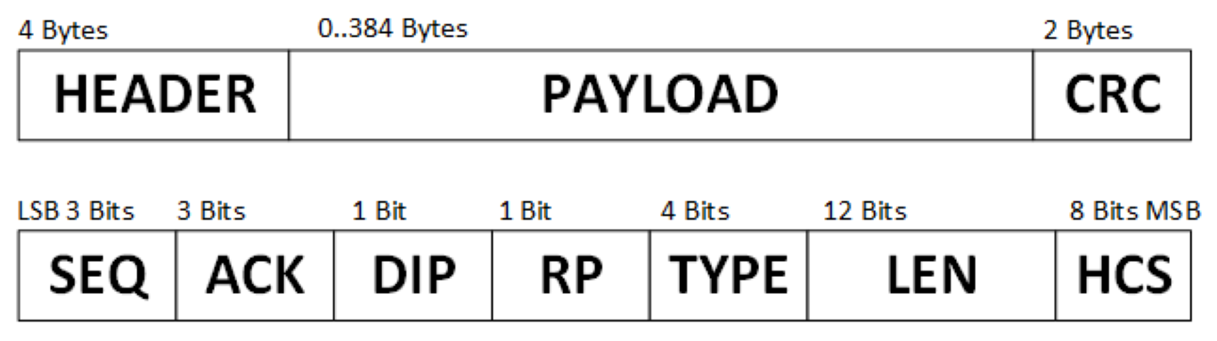
Packet format complies with the standard, yet because of memory shortage in the connectivity chip, current implementation limits packet size to 384 bytes.
Every payload packet consists of 4-byte header followed by payload and CRC field.
Packet header contains SEQ, ACK numbers, DIP (data integrity check), RP(reliable packet) flags, LEN - numbers of bytes in the payload and HCS - header checksum.
Payload packet use TYPE=0xE - vendor specific type. Acknowledgement packets use TYPE=0x0, SEQ=0, DIP=0, RP=0, LEN=0.
The basic communication flow implemented in HCI layer is shown in a figure below.
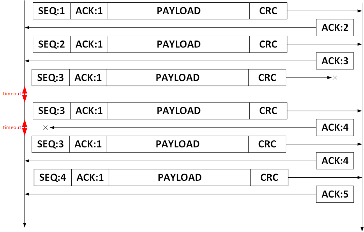
Each payload packet requires an acknowledgement to complete a transmission. An acknowledgement packets has an ACK field set to number, which indicates next expected SEQ number.
When an acknowledgement packet is not received within time-out window, packet is retransmitted.
When a packet with invalid SEQ is received (for example, for retransmitted packet due to lost acknowledgement packet), receiver sends an ACK to indicate next expected packet.
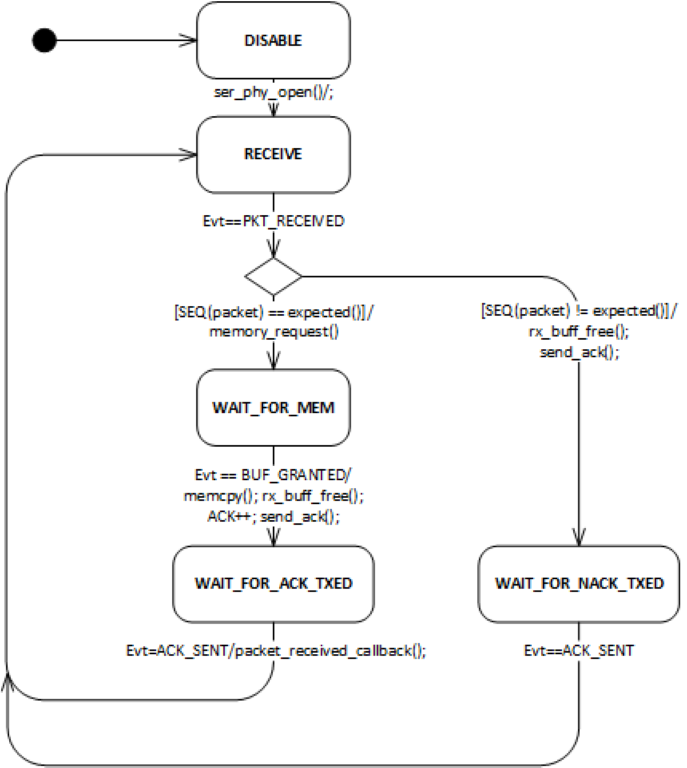
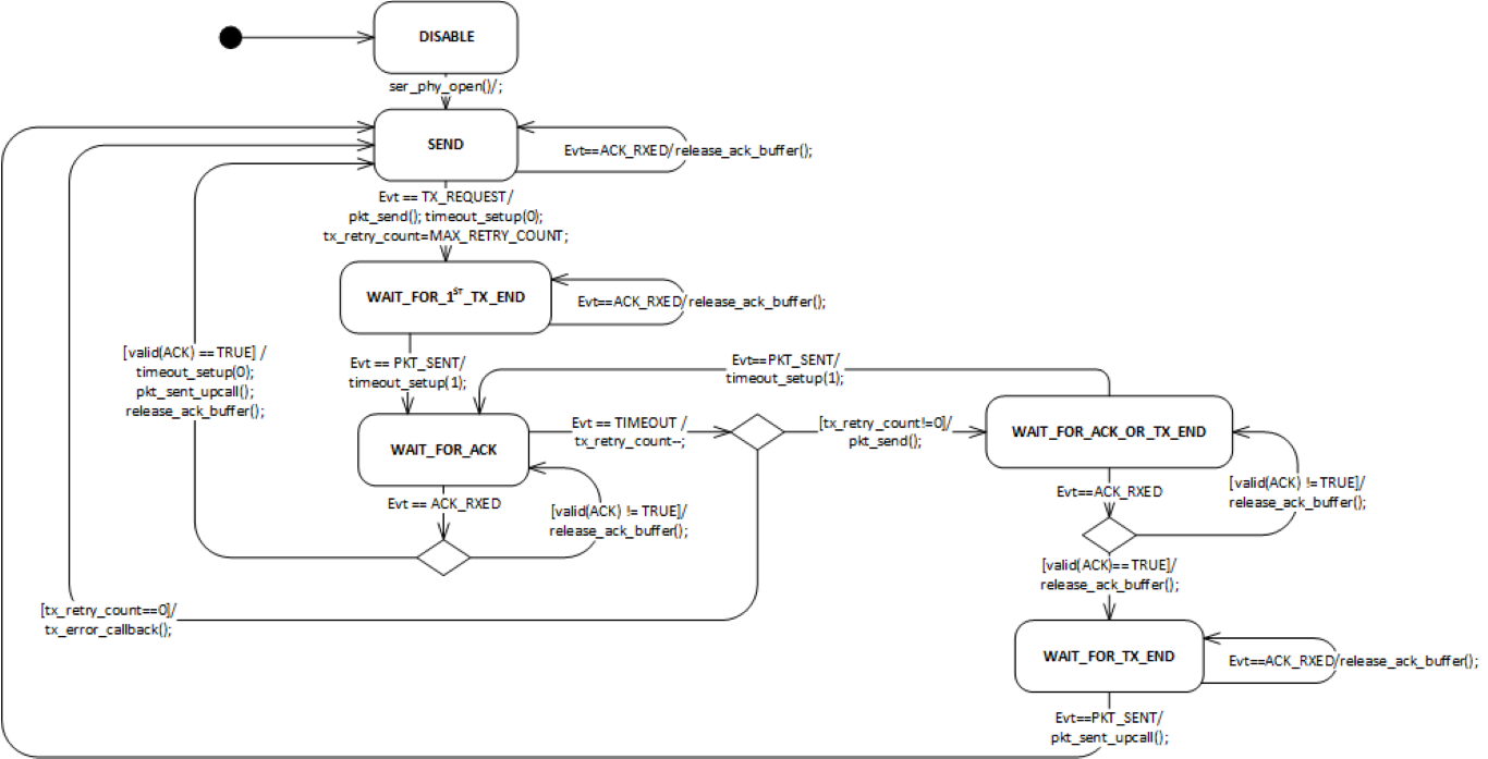
Driver is splitted into two layers - HCI and SLIP.
HCI layer is implemented as two event driven state machines with separated micro schedulers for events coming from SER_PHY, SLIP layers, and timer.
The operation of receiver and transmitter state machines is shown below as UML state diagrams.
Packets are transmitted in the following format :
TX_HCI_SLIP_PACKET = [TX_PACKET_START][TX_PAYLOAD][TX_PACKET_END] where both TX_PACKET_START and TX_PACKET_END are 0xC0 byte.
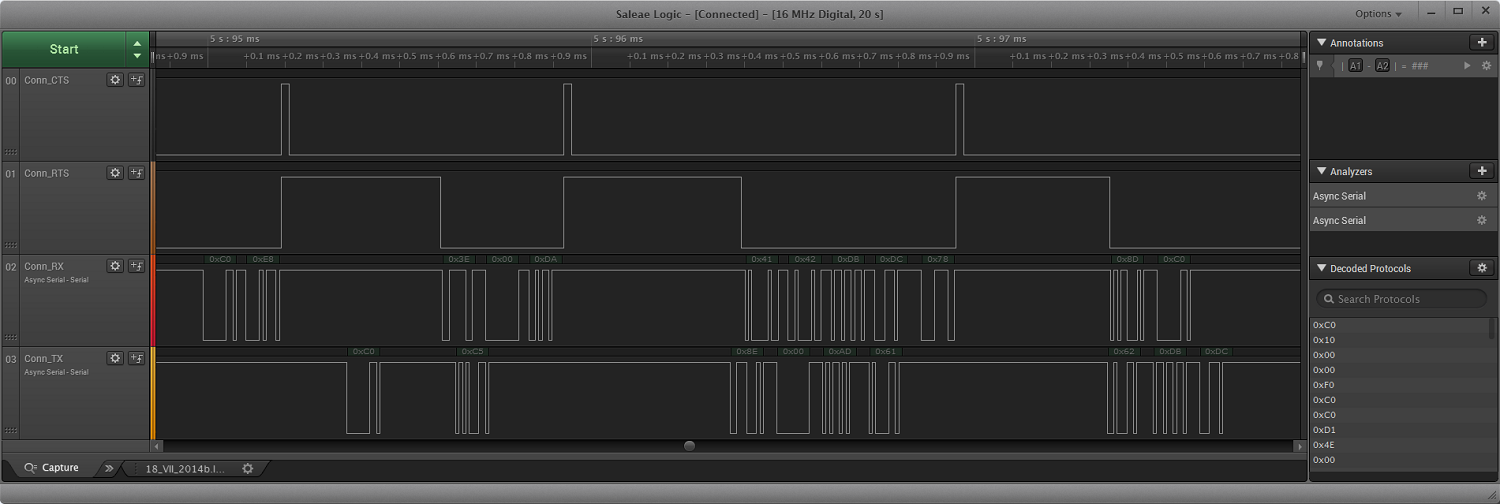
On the RX line reception of a complete SLIP packet can be observed. [RX_PACKET]=[0xC0 0xE8 0x3E 0x00 0xDA 0x41 0x42 0xDB 0xDC 0x78 0x8D 0xC0] At the beginning and the end of the packet there are 0xC0 bytes which indicate packet start and packet end. Between both 0xC0 symbols the content of the packet is received. It includes higher level (HCI) header, CRC and payload. There is also a SLIP escape sequence present: [0xDB 0xDC] which is an encoded 0xC0 character. On the TX line a part of a SLIP packet is shown.
UART HCI SLIP protocol for serialization is implemented in 'ser_phy_uart_hci_slip.c' file. It uses 'app_uart.c' as a low-level UART driver.
The implementation is event-driven. Events from the low-level driver are handled in static 'ser_phy_uart_evt_callback()' function. Three types of app_uart_evt_t
events are processed: APP_UART_COMMUNICATION_ERROR, APP_UART_TX_EMPTY, APP_UART_DATA.
Following ser_phy_hci_slip_evt_type_t events are send to upper layer:
Function ser_phy_hci_slip_open() initializes UART using APP_UART_INIT macro with configuration structure of type app_uart_comm_params_t as input. It also registers SER_PHY_HCI_SLIP event callback.
Function ser_phy_hci_slip_close() closes UART using app_uart_close() function. It also de-registers SER_PHY_HCI_SLIP event callback.
 1.8.3.1
