 |
nRF51 SDK - S120 SoftDevice
|
|
nRF51 SDK - S120 SoftDevice
|
SPI_5W RAW protocol implements Serialization PHY API for SPI interface.
In 5W implementation SPI interface uses 5 lines: four standard (CLK,MOSI,MISO,/CS) and one additional - /RDY.
Application processor is a SPI bus master, nRF51 chip acts as a slave device.
In principle, the operation of SPI_5W is similar to standard 6 wire implementation ( SPI RAW protocol ).
The major difference is lack of /RDY line, which in 6 wire implementation is used to indicate readiness of slave device for a data transaction.
Without /RDY line master device has to speculate by initiating transfer without prior knowledge if slave device is ready to accept data.
To distinguish a transactions with slave device, which is ready for data, from transactions with slave device, which is not ready for data, a signalling on MISO line is used.
nRF51 SPI slave device hardware clocks out DEFAULT byte (programmed as [0xFF]) , when device is not ready for data transaction.
Since, only MISO line is used for signalling of READY state, it works slightly differently for writing and reading operation.
For packet writing, signalling is straightforward, when slave device is ready for data, it clocks out zero [0x00] for all data bytes.
The same rule applies when packet is read, but only for the first byte in each transaction.
Physical layer driver precedes each reading transaction with 'guard byte' [0x00].
If during read/write operation master detect invalid (nonzero) 'guard byte', transaction is aborted (/CS is deasserted) and master device initiates a new transaction.
Backoff is determined by time needed for processing interrupts and resetting internal state machines.
The size of MTU defines size of physical frames. Due to the 'guard byte' overhead, the effective frame size is smaller by 1 byte in reading transactions.
The SPI_5W driver is controlled by 'SPI_5W' flag.
If __SPI_5W__ flag is not defined, line /RDY is used as in standard 6 wire implementation, yet with frames including 'guard byte'.
Packets are transmitted in a following format :
TX_RAW_PACKET = [TX_HEADER][TX_FRAME][TX_FRAME][TX_FRAME]...
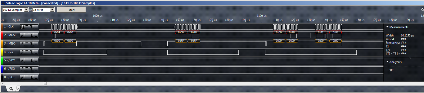
Packet length is send as a [TX_HEADER]=[0x0004] in the first transaction.
Since, first byte of data clocked in [0x0000] is a valid 'guard byte', transaction is considered to be successful.
Second transaction attempts to transfer payload [TX_FRAME]=[0x00, 0x78, 0x41, 0x03], but due to invalid 'guard byte', is aborted.
During third transaction valid 'guard byte' is clocked in and transaction is completed.
Note, that /RDY line is deasserted during transaction, because it is not driven by slave device.
Packets are received in a following format:
SPI_RAW_PACKET = [ZERO_HEADER][RX_HEADER][RX_FRAME][RX_FRAME][RX_FRAME]...
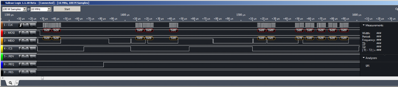
Slave request for reading of a packet is signalled by assertion of /REQ line.
When master device is ready to read a packet, it sends a [ZERO_HEADER] =[0x0000].
[ZERO_HEADER] is used as indication, that master device initiates a packet read operation.
When [ZERO_HEADER] is detected by slave, /REQ line is deasserted.
In the next transaction [RX_HEADER] =[0x00][0x0006] is read.
First byte in [RX_HEADER] is a valid 'guard byte', which indicates that remainder of payload has meaningful data.
In third transaction 'guard byte' together with a payload of 6 bytes [0x00][0x01, 0x78, 0x00, 0x00, 0x00, 0x00] is clocked in.
SPI_5W RAW protocol for master device is implemented in ser_phy_nrf51_spi_5W_master file.
The operation of ser_phy_switch_state() is almost identical as for standard driver Master device driver, except for the fact, that slave device is assumed to be always READY. Therefore, when interpreting a graph, one should assume that, RDY flag is always TRUE and there will be no RDY_EVT event. Once transaction is scheduled by PHY driver, its execution is controlled by adaptation state machine, which captures events from hardware driver. Operation of adaptation state machine is illustrated by UML state diagram .
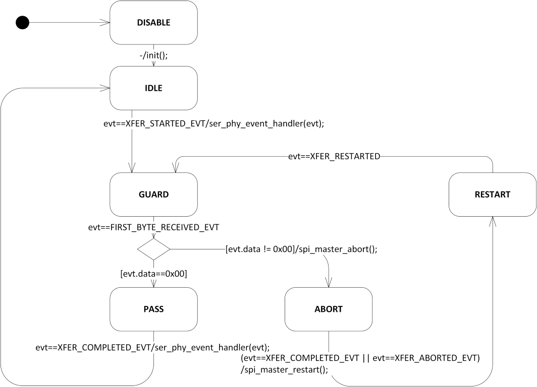
If __SPI_5W__ flag is not defined, adaptation layer is disabled and line /RDY is used as in standard 6 wire implementation
SPI RAW protocol for slave device is implemented in ser_phy_nrf51_spi_5W_slave file.
The operation spi_slave_event_handle() is almost identical as in standard driver Slave device driver, except for the line /RDY is not driven.
If __SPI_5W__ flag is not defined, line /RDY is used as in standard 6 wire implementation
 1.8.3.1
