Dynamic Pin Control (nRF)
The Dynamic Pin Control (nRF) sample demonstrates how to change uart0 at
early boot stages, depending on the input level on a pin connected to a
push-button.
Overview
Slightly different board revisions that implement just small changes (like improving the PCB layout or changing components to new equivalents) do not necessarily require changes to the firmware. As such, one firmware image can be able to boot onto multiple board revisions.
However, if a certain peripheral is routed to different sets of pins between revisions, the firmware needs to select the appropriate routing when the system is initialized.
The Dynamic Pin Control (nRF) sample allows you to select the appropriate routing.
If the push button is not pressed, the system does nothing and continues with the default configuration. If the button is pressed, the alternative configuration is applied.
Alternative configurations can only be applied if the device driver using the
associated pins has not been initialized yet. Therefore, pay attention to the
initialization priorities set in the prj.conf file.
nRF52840 DK
The diagram below shows the pins assigned to the default and alternative configurations.
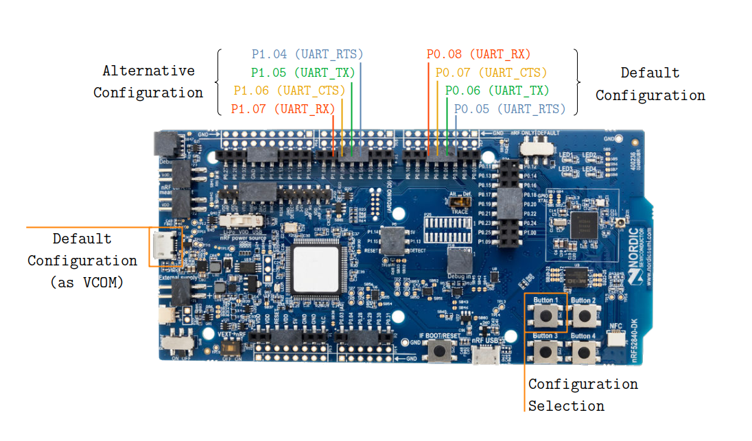
Configuration for nRF52840 DK
If you power on the board, the uart0 peripheral is routed to the default
set of pins. The default set of pins is also exposed through the left USB
connector as a virtual COM port.
If you power on the board while holding Button 1, the uart0 peripheral is
routed to the alternative set of pins.
Building and Running
You can build this application for the nRF52840 DK as follows:
west build -b nrf52840dk_nrf52840 samples/boards/nrf/dynamic_pinctrl
The sample can also support other nRF based boards if you provide a Devicetree
overlay file with an alternative configuration for uart0. Select uart0
for zephyr,console to make the sample work as expected.
Sample Output
Follow these steps to test the two configurations :
Connect a USB-to-UART adapter to both sets of pins. If the board routes the default configuration to a virtual COM port (as in the nRF52840 DK), you can directly use that port.
Open two serial terminals, one connected to the default set of pins and the other connected to the alternative set of pins.
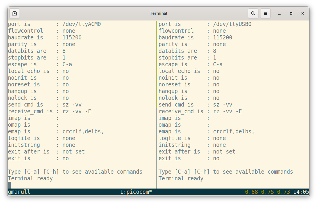
Two serial terminals (left: default, right: alternative).
Turn on the board. You should see a
Hello World!message printed on the first terminal.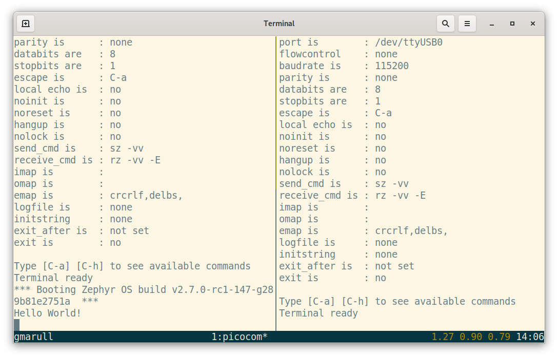
Hello World!printed on the default set of pins.Press and hold the configuration-selection push-button (button 1 on the nRF52840 DK) and press the board reset button. You now should see a
Hello World!message on the second terminal.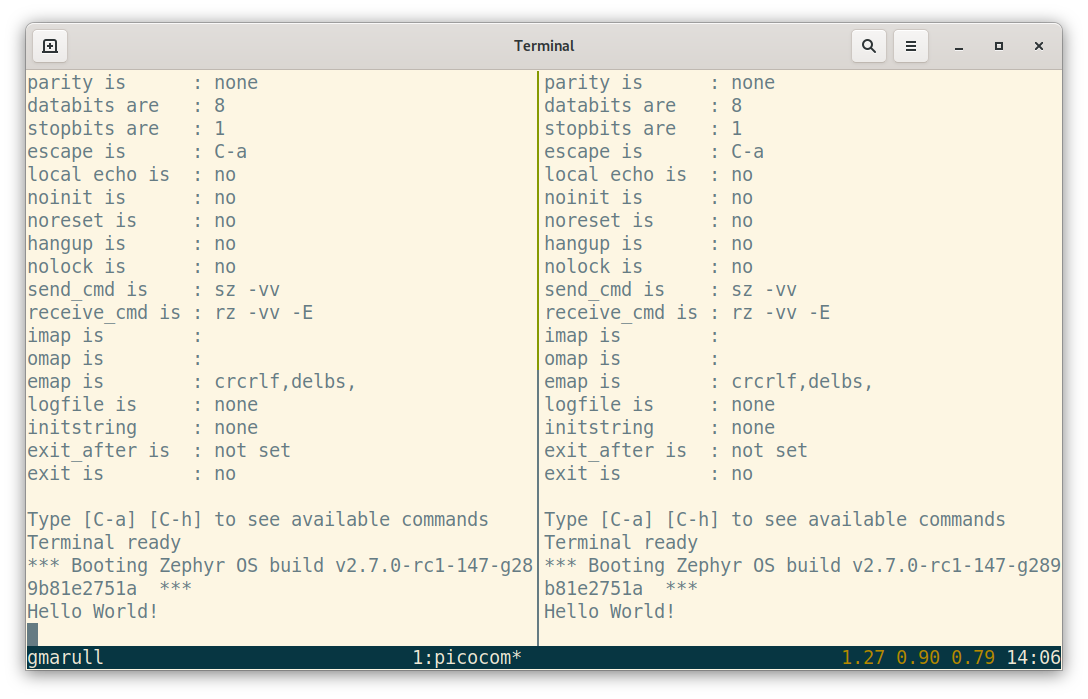
Hello World!printed on the alternative set of pins.